 |
Application of FIB "Plan-View Lift-Out" Technique
|
 |
|
|
|
Site-specific TEM Specimen Preparation of
Grain Boundary Corrosion in Nickel-Based Alloys Using the FIB "Plan-View Lift-Out" Technique |
|
|
|
|
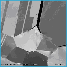
FIG. 1. FIB secondary electron image (SEI) of the terminus of grain boundary corrosion (which appears black as it is an insulator) in a Ni-based alloy. Field of view = 80mm.
|
FIG. 2. FIB secondary ion image (SII) of the region shown in Figure 1. Oxygen enhanced ionization yield increases the signal from the corroded regions making them appear white.
|
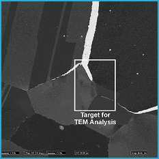
FIG. 3. FIB SII after a thin protective layer of FIB tungsten is deposited over the region of interest. This tungsten also serves as a marker of the original surface. FOV = 80 mm.
|
|
|
|
|
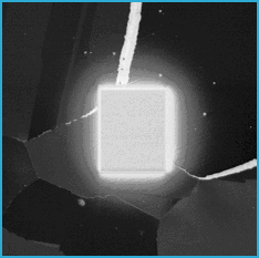
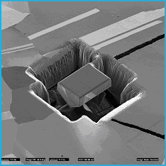
FIGs. 4 & 5. Top and off-axis views (FIB SEI) of the "inverted barn" milled free of the surrounding material. A small support (top right) holds the barn in place until final trimming just prior to lift-out. The region to be removed is 25mm x 20mm at its base which is still covered by a protective tungsten coating.
|
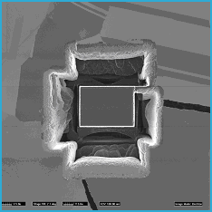
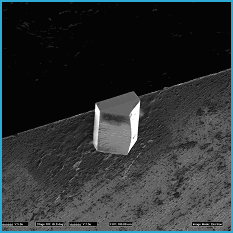
FIG. 6. FIB SEI of the "barn" glued down on the carrier, ready for thinning to electron transparency.
|
|
|
|
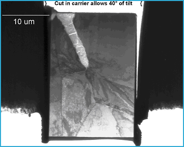
FIG. 7. TEM BF image (originally 1,500X) of the final specimen mounted on the carrier. Compare to FIGs. 2 & 3.
|
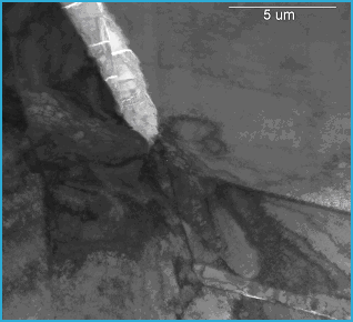
FIG. 8. TEM BF image (originally 3,810X) of the tip of the corrosion and the unattacked portion of the g.b.
|